


News
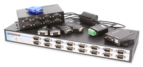
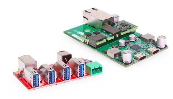
Serial RS-232, RS-422, RS485 Adapters
The Serial RS-232 Signal Difference
RS-232, RS-422, RS-485 Information
We receive many support calls with regard which serial adapter is needed for a particular serial application. RS-232 connections are the physical interfaces in which one data bit of information is transmitted to serial communication devices such as modems, terminals, Ethernet devices and other various types of peripherals. It is the standard in serial communication. While higher speed capabilities have been developed using USB and Firewire, the standard DB-9 Pin serial port has remained in industry.
RS-232 DB-9 pin out diagram.
| PIN | SIG. | Signal Name | DTE (PC) | 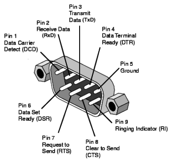 |
| 1 | DCD | Data Carrier Detection | IN | |
| 2 | RXD | Receipt of Data | IN | |
| 3 | TXD | Transmit Data | OUT | |
| 4 | DTR | Data Terminal Ready | OUT | |
| 5 | GND | Signal Ground | – | |
| 6 | DSR | Data Set Ready | IN | |
| 7 | RTS | Request to Send | OUT | |
| 8 | CTS | Clear to Send | IN | |
| 9 | RI | Ring Indicator | IN |
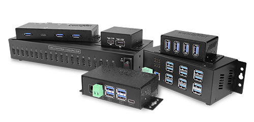
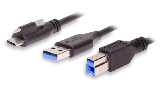
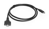
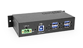
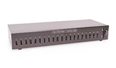
USB to Serial Adapters in general are manufactured in many forms from molded cables, mini adapters, single port, multi-port, industrial metal chassis, and plastic less rugged cases.
Serial Signal Difference
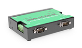
RS-232 Adapters
On the technical side of the differences, RS232 is a single-ended signal with a specification that allows for data transmission from one transmitter to one receiver at a fairly slow data rate of up to 20K bits/second over short distances of up to 50Ft. using a maximum data rate. RS232 signals are represented by voltage levels with respect to a system power / logic ground. The “idle” state has the signal level negative with respect to common (signal ground in chart above), and the “active” state has the signal level positive with respect to common.
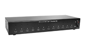
RS-422 Adapters
RS-232 doesn’t interpret well when communicating at higher data rates and over longer distances in actual day-to-day usage environments. RS-422 compensates in its wiring compared to RS-232 to create “differential data transmission” or balanced differential signal.
RS-422 incorporates much better performance in most serial applications; using differential signals can help invalidate the effects of ground shifts and induced noise signals. These signals can sometimes appear as common mode voltages on a network; RS-422 recognizes this noise and produces a much clearer and accurate signal. Signal modes such as RS-422 and RS-485 can also be selectable via DIP Switch or Terminal Wire which is directly wired to a Terminal Block from an outside source.
The RS-422 differential data transmission is designed for 100Kbps and for transmitting at distances of up to 4000 Ft. RS422 is also designated for multi-drop “party-line” communication applications where there is only one driver connected to and transmits on, a “bus” of up to 10 receivers. See the RS-422 wiring diagram below:
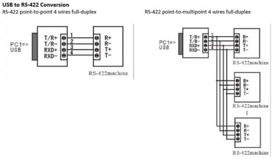
Data Signals Supported by RS-422 and RS-485
- RS-422 data signals: TxD-, TxD+, RxD+, RxD-, GND, RTS-, RTS+, CTS+, CTS-
- RS-485 4-wire data signals: TxD-, TxD+, RxD+, RxD-
- RS-485 2-wire data signals: Data-, Data+
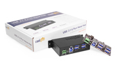
RS-485 Adapters
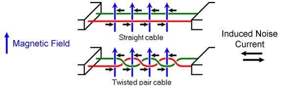
RS-485 signal adapters are basically a go between from the converters to the terminal or PC using RS-485 signal levels, in other words, the format, speed, and protocol of the data during transmission is not governed by RS-485. The similarity between devices from various manufacturers does not assure compliance with the signal levels by itself. The RS-485 signal is a two wire system that is either a straight or twisted pair wiring construction with a maximum of 32 transmitters and receivers can be operated. RS-485 also keeps the 100Kbps over a length of 4000 ft. transmission rate that the RS-422 specification does. See the straight and twisted pair wire diagram below:
Fortunately as mentioned in the beginning of this post, there are many different types of serial cables, adapters, or converters for completely different types of serial application uses. Because of the transmit and receive functions of all these serial signal types, troubleshooting data transmission if needed is generally done by reading the adapter’s RXD/TXD LED indicators if provided on the device.